Showing posts with label Arduino. Show all posts

Sunday, July 8, 2012

Whiteboard Clock


Introduction

I have been working on a calculator for my girlfriend, but unforeseen complexity has caused the project to stretch out over months rather than weeks. In place of finishing the calculator, I came up with a more simple, more useful project (birthday present) which has the potential to be profitable if the design is tweaked to be easier to manufacture. This post contains (1) a video of the finished product (2) followed by background information (3) followed by a gallery detailing each step of the build process and (4) finally the Arduino code behind the functionality.


Lizz's Whiteboard Clock


Background

Each led requires a high signal to turn on. This means that I need a total of 72 separate signals to turn on each led individually. However an Arduino only has 14 digital output. If we consider using pins in combinations there are a few methods of controlling large number of signals using a small number of I/O ports.

  1. Multiplexing: This allows a microprocessor to control 2^n signals with n outputs. These are used heavily when building custom hardware (verilog, VHDL, etc.) but there are not large IC chips available. I would have to string multiple smaller DEMUX chips together to achieve a 7 bit DEMUX.
  2. Charlieplexing: This allows a microprocessor to control n(n-1) signals with n outputs. Charlieplexing relies on the fact that LED are directional i.e. they will only turn on when a voltage is applied to then in the correct direction. This means that we can have an LED hooked up to pin 1 and 2 and another LED hooked to pin 2 and 1 while turning them on or off independently.
Both of these methods allows for a single LED to be turning on at any given time. However, for a clock we need at most 2 or 3 LEDs turned on at once (hours, minutes, seconds). We can accomplish this using persistence of vision. Most video on the internet is only 30 frames per second (updates 30 times a second) because the human eye cannot perceive changes faster than that. This means that if we update the clock 30 times per second while cycling through hours, minutes and seconds, then we can make each LED appear to be on simultaneous to the other two. There are specialized chips which do this (MAX7221) for 7-segment display and LED dot-matrices.


The Build


The Code

LizzClock.h

#ifndef LIZZCLOCK_h
#define LIZZCLOCK_h


typedef struct LED {
  char high;
  char low;
} LED;

typedef struct BUTTON {
  long down;
  char set;
  char PIN;
} BUTTON;


typedef struct TIME {
  char hours;
  char minutes;
  char seconds;
} TIME;

#endif

LizzClock.ino

#include "LizzClock.h"
#include <TimerOne.h>

#define TRUE    1
#define FALSE   0

// Display Constants
#define OFFSET  2

LED lights[72];
LED* curr_led = 0;
char PAUSE = 50;
char BRIGHTNESS = 0;
int UPDATE_COUNT (100/PAUSE);
int ON_DELAY = PAUSE;
int OFF_DELAY = 0;

TIME *curr_time;
long start_time;

BUTTON *minutes_button;
BUTTON *hours_button;

void setup() {
  /*
   * Initalize current time and update interrupt
   */
  start_time = millis();
  curr_time = (TIME*) malloc(sizeof(TIME));
  curr_time->seconds = 0;
  curr_time->minutes = 0;
  curr_time->hours = 0;
  Timer1.initialize(100000);
  Timer1.attachInterrupt(update_time);

  /*
   * Initalize buttons
   */
  minutes_button = (BUTTON*)malloc(sizeof(BUTTON));
  minutes_button->down = 0;
  minutes_button->PIN = 12;
  pinMode(minutes_button->PIN, INPUT);
  hours_button = (BUTTON*)malloc(sizeof(BUTTON));
  hours_button->down = 0;
  hours_button->PIN = 13;
  pinMode(hours_button->PIN, INPUT);

  /*
   * Initalize display
   */
  set_brightness(30);  

  /*
   * MINUTES/SECONDS
   */
  init_LED( 0, 0, 1); // 0  and 1
  init_LED( 2, 0, 2); // 2  and 3 
  init_LED( 4, 1, 2); // 4  and 5
  init_LED( 6, 0, 3); // 6  and 7
  init_LED( 8, 1, 3); // 8  and 9
  init_LED(10, 2, 3); // 10 and 11
  init_LED(12, 0, 4); // 12 and 13
  init_LED(14, 1, 4); // 14 and 15
  init_LED(16, 2, 4); // 16 and 17
  init_LED(18, 3, 4); // 18 and 19
  init_LED(20, 0, 5); // 20 and 21
  init_LED(22, 1, 5); // 22 and 23
  init_LED(24, 2, 5); // 24 and 25
  init_LED(26, 3, 5); // 26 and 27
  init_LED(28, 4, 5); // 28 and 29
  init_LED(30, 0, 6); // 30 and 31
  init_LED(32, 1, 6); // 32 and 33
  init_LED(34, 2, 6); // 34 and 35
  init_LED(36, 3, 6); // 36 and 37
  init_LED(38, 4, 6); // 38 and 39
  init_LED(40, 5, 6); // 40 and 41
  init_LED(42, 0, 7); // 42 and 43
  init_LED(44, 1, 7); // 44 and 45
  init_LED(46, 2, 7); // 46 and 47
  init_LED(48, 3, 7); // 48 and 49
  init_LED(50, 4, 7); // 50 and 51
  init_LED(52, 5, 7); // 52 and 53
  init_LED(54, 6, 7); // 54 and 55
  init_LED(56, 0, 8); // 56 and 57
  init_LED(58, 1, 8); // 58 and 59

  /*
   * HOURS
   */
  init_LED(60, 2, 8); // 12 and 1
  init_LED(62, 3, 8); // 2  and 3
  init_LED(64, 4, 8); // 4  and 5
  init_LED(66, 5, 8); // 6  and 7
  init_LED(68, 6, 8); // 8  and 9
  init_LED(70, 7, 8); // 10 and 11
}

/*\\\\\\\\\\\\\\\\\\\\\\\\\\\\\\\\\\\\\\\\\\\\\\\\\\\\\\\\
 *      [[  DISPLAY INIT START  ]]
 */

char set_brightness(int new_brightness) {
  if (new_brightness >= 0 && new_brightness <= PAUSE) {
    BRIGHTNESS = new_brightness;
    ON_DELAY = (PAUSE > BRIGHTNESS ? PAUSE - BRIGHTNESS : 0);
    OFF_DELAY = (PAUSE < BRIGHTNESS ? PAUSE : BRIGHTNESS);
    return TRUE;
  }
  return FALSE;
}

void init_LED(char index, char high, char low) {
  lights[index+1].high = high;
  lights[index+1].low = low;
  lights[index].high = low;
  lights[index].low = high;
}
//      [[  DISPLAY INIT END  ]]
//////////////////////////////////////////////////////////


/*\\\\\\\\\\\\\\\\\\\\\\\\\\\\\\\\\\\\\\\\\\\\\\\\\\\\\\\\
 *      [[  EXECUTION START  ]]
 */
void loop() {
  // update_time called on timed interrupt 10 times a second
  display_time(curr_time);
  check_user_set_time();
}
//      [[  EXECUTION END  ]]
//////////////////////////////////////////////////////////


/*\\\\\\\\\\\\\\\\\\\\\\\\\\\\\\\\\\\\\\\\\\\\\\\\\\\\\\\\
 *      [[  MAINTAIN DISPLAY START  ]]
 */
LED* get_hour(char hour) {
  if (hour <= 0 || hour >= 12)
    return &lights[60];
  return &lights[hour + 60];
}

void all_off()
{
  for(int i = 2; i < 12; i++) {
    pinMode(i, INPUT);
    digitalWrite(i, LOW);
  }
}

char get_pin(char index) {
  return index + OFFSET;
}

void display_time(TIME *time) {
  lightup(&lights[time->seconds]);
  lightup(&lights[time->minutes]);
  lightup(get_hour(time->hours));
}

void lightup(LED* led) {
  // blank display and pause to control brightness
  all_off();
  delayMicroseconds(OFF_DELAY);
  //delayMicroseconds();

  // turn on display for short time to allow for persistance of vision.
  pinMode(get_pin(led->high), OUTPUT);
  digitalWrite(get_pin(led->high), HIGH);
  pinMode(get_pin(led->low), OUTPUT);
  digitalWrite(get_pin(led->low), LOW);
  curr_led = led;
  delayMicroseconds(ON_DELAY);
}
//      [[  MAINTAIN DISPLAY END  ]]
//////////////////////////////////////////////////////////


/*\\\\\\\\\\\\\\\\\\\\\\\\\\\\\\\\\\\\\\\\\\\\\\\\\\\\\\\\
 *    [[  MAINTAIN CLOCK START  ]]
 */
void update_time() {
  long temp = (millis() - start_time) / 1000.0;
  //long temp = (millis() - start_time) / 3;
  curr_time->seconds = temp % 60;
  temp /= 60.0;
  curr_time->minutes = temp % 60;
  curr_time->hours = temp / 60.0;
  if (curr_time->hours == 12) {
    curr_time->hours = 0;
    // assume time is updated more than once a second.
    start_time = millis() - (curr_time->seconds * 1000);
    //start_time = millis() - (curr_time->seconds * 3);
  }
}

void check_user_set_time() {
  if (digitalRead(minutes_button->PIN)) {
    // if button down
    if (minutes_button->down) {
      // if currently debouncing
      if (!minutes_button->set && millis() - minutes_button->down > 20) {
        // if debounced long enough
        start_time -= 60000; // seconds * milliseconds
        minutes_button->set = 1;
      }
    } 
    else {
      // start debouncing
      minutes_button->down = millis() ^ 1;
    }
  } 
  else if (minutes_button->down) {
    minutes_button->down = 0;
    minutes_button->set = 0;
  }
  if (digitalRead(hours_button->PIN)) {
    // if button down
    if (hours_button->down) {
      // if currently debouncing
      if (!hours_button->set && millis() - hours_button->down > 20) {
        // if debounced long enough
        start_time -= 3600000; // minutes * seconds * milliseconds
        hours_button->set = 1;
      }
    } 
    else {
      // start debouncing
      hours_button->down = millis() ^ 1;
    }
  } 
  else if (hours_button->down) {
    hours_button->down = 0;
    hours_button->set = 0;
  }
}
//      [[  MAINTAIN CLOCK END  ]]
//////////////////////////////////////////////////////////

Thursday, June 14, 2012

Towel Build and Parts

The Towel is a simple RC delta wing poularized by Brooklyn Aerodrom and MAKE Online. It is a simple build for under $100 that should allow flight in only a few hours work. I stumbled across HobbyPartz.com which has amazing deals on robotics, RC and hobby electronics parts.

The following parts are either on their way for my Towel build or worthy of mention: 


  • 2.4G FlySky 6-Channel TX/RX Combo for $33 [[ Here ]] 
  • 2.4G FlySky 6-Channel Receiver for $9 [[ Here ]] 
  • Brushless Motor (KV 1300) + 18A ESC + 3 x 9g Servos for $25 [[ Here ]] 
I will post as progress is made. However, research will not let that happen anytime soon...

Saturday, June 9, 2012

Lizz's Calculator - Software Update

Reminder
As a reminder, I am building a custom calculator with an Arduino as a brain. This will use four linear time algorithms for pre-parsing the equation and a context free grammar to define valid syntax with a recursive descent parser to evaluate the equations. Note that each time the application is redesigned I am changing the version numbers so that I can more easily compare my documentation. Version 0.1 is implementing recursive pre-parsing and currently ignoring high precision requirements* for fast development and greater overall simplicity.

*This can (semi-)easily be fixed later using 3rd party libraries or implementing a custom library which implements big_floats by keeping track of a numerator and denominator, each in scientific notation.

Pre-Parsing
The pre-parsing code is complete, tested and committed to the repository.  The following algorithms serve to sanitize the input; ensuring the syntax passed to the recursive descent parser can be parsed by the grammar efficiently and accurately. The pre-parsing process is completed as follows.

  1. Parses a string (char*) and convert each equation element to a node inside a doubly linked list. Each number is parsed and converted to a float, each multi-character operation is converted to a single node with an identifying character e.g. SIN(...)->'s', LOG(...)->'g', etc. . 
  2. Once the equations is parsed into a linked lists, an algorithm uses a stack to ensure parentheses matching. While performing this check, an instance variable in each node containing a parentheses is set to specify its corresponding parentheses. 
  3. A third algorithm is used to surround each argument of two-argument operations with parentheses if necessary. This is done recursively keeping track of the insert position of the left parentheses and searching for operations to specify the position for the closing parentheses e.g. '+', '-', '*' and '/'. To ensure correct order of operations, this parsing is done on addition and subtraction, then re-evaluated on multiplication and division. Note that this step is not required for exponents or single argument operations e.g. SIN, COS, etc. . The algorithm includes checks to avoid duplicate or nested parentheses using the "match" instance variable, set in step 2, in each node containing a parentheses e.g. avoid "((3))+((4))".
Current UML
This will grow quickly as hardware is added; the project is still pending 128x64 pixel display, 5-bit 30-button array and power management including power button and low power state.


Evaluating The Equation
The current grammar is currently being redesigned as an LL(1) or LL(2) context free grammar. The current grammar is far too ambiguous to evaluate equations efficiently. I will post updates as progress is made, but I have multiple large research deadlines approaching in the next two weeks.

Friday, June 1, 2012

Lizz's Calculator - Build Update

This is an update from the previous design post which can be found here.

Software:

The code repository can be found here. All information found in updates on this blog will also be included in the README file for proper documentation. An old version or the parser which linearly parses the equation. This was originally written for a 32-bit PIC chip.

Electronics:

Recall that I had the "complexity" requirement (look as crazy as possible, with wires everywhere!). I think it is working out nicely. The schematics can be found on the design post linked above.


Lizz's Calculator - Design

My girlfriend just graduated from Georgia Tech as a math major. So obviously, she wants a custom calculator for her birthday...

I am planning to design and build a calculator in multiple versions which will have the functionality of a scientific calculator in v1 and a rudimentary graphing calculator in v2. This blog will chronicle the design and build process of Lizz's calculator with an Arduino as the brain.

Functionality (v1)

  • Order of operations including parenthesis
  • Algebra and geometric functions
  • High precision (more accurate than double precision)

Design

Software

The calculator will use a recursive descent parser with 3 stages of pre-parsing to validate and evaluate complex equations. The following context free grammar will define the language of valid equations:


    <S>     : <ex>
    <ex>    : (<ex2>) | <ex2>
    <ex2>   : <arg> | <op2> | <op1>
    <op2>   : <ex> <_op2> <ex>
    <_op2>  : + | - | * | / | ^
    <op1>   : <_op1>( <ex> )
    <_op1>  : SQRT | LOG | LN | <geo>
    <geo>   : <geo2> | ARC<geo2>
    <_geo>  : SIN | COS | TAN
    <arg>   : <num> | <num>.<num> | <const>
    <num>   : [0-9]+
    <const> : E | PI

The pre-parsing processes is defined as follows:

   Pre-Parse Rules:
   ----------------
    1. Surround all { +, - } args with ()'s recursively
        e.g. 8*3^4+PI => (8*3^4)+(PI). Note that recursion
        is used inside other sets of parentheses.
    2. Surround all { *, / } args with ()'s recursively
        e.g. (8*3^4)+(PI) => ((8*3)^4)+(PI). Note that recursion
        is used inside other sets of parentheses.
    3. Remove all unessary parentheses e.g. ((3+4)) => (3+4).
        These will cause a parsing error.
   
   NOTE: that these techniques are used to ensure order of 
   operations. The parentheses force the correct order of 
   operation when using the grammar above i.e. respect user 
   parentheses by using recursion, respect exponents by not 
   surrounding with parentheses, respect *,/ then respect +,- by 
   order of adding extra parentheses.


The software architecture is a simple recursive descent parser.


Electronics

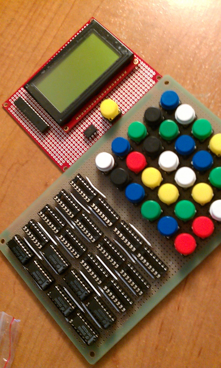
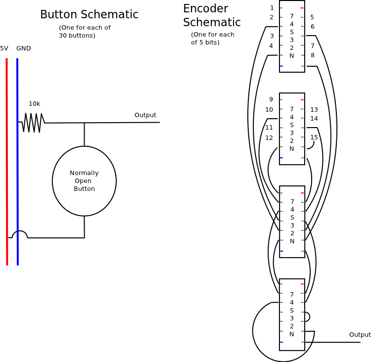
The electronics will use an ATMEGA328 processor (Arduino UNO) for computations. One odd requirement for electronics design is that my girlfriend wanted the calculator "to look as crazy as possible, with wires everywhere!". So, I am make the design a little diluted and more complicated than necessary, hence me building my own 30 button array and 30:5 bit encoder. See schematics and block diagrams below


Wednesday, May 9, 2012

Bindary - Binary Wrist Watch

Overview

The Bindary wrist watch is meant to be an easy, do-it-yourself project which allows users to build a novel wrist watch with basic functionality. This serve as a side project during Summer 2012 while I am taking math classes and would rather be working with CS and electronics.

Feature and Requirements

The Bindary watch will implement the following functionality:
  • Settable time including {second, minute, hour, day, month}
  • Auto-adjusting brightness with programmable override brightness
  • Toggle 12-hour and 24-hour time format
  • Toggle binary and scroll mode
  • Scroll Mode
    • Programmable scroll speed

Parts

Estimated Parts Cost: $14.00

Technologies

SPI - Serial Peripheral Interface. 4-wire serial communication.

Implementation


The following state machine represents the state transitions which will allow the defined functionality an user input. TODO: Add state for setting brightness.

While setting values the corresponding columns will be blinking. While setting brightness, the whole display will blink. While setting "Scroll/Binary" a large "S" or large "B" will be displayed. While setting the speed of scroll mode, the time will read "00:00am 00/00"


Notes

Note that a recent change has "DAY" representing the day of the month. This now requires 5 bits rather than 3 bits to represent days of the week. Therefore the "spinner" will be replaced by a "flashing" top row.


S800G Mod

Eventually...

Eventually I would like to slowly remove the structure and replace it with lightweight protoboards allowing for on-board computation. Using an ATMEGA328, a gyro, two IR sensors and an extended battery pack, I hope to build an autonomous wall following copter. Basic algorithms should allow it to navigate slowly and with a simple state machine. However a more advanced application will allow for more aggressive motion with the possibility of racing and obstacle courses.


Introduction:

I am working to improve the battery life and in turn flight time of my S800G radio controlled helicopter. If you remove the front covering you will see that the battery is a 3.7V 150mAh Li-ion battery.

With any experience in hobby electronics you will know that most Li-ion batteries have a 3.7V nominal voltage. So after checking a few old cell phones I found some replacement batteries. Originally I tried an old HTC 1230mAh. Before connecting the power terminals I attempted to mount it in multiple positions (to maintain the same center of gravity). However, it was easy to see that the battery simple weighted too much and would not let the copter take off. I have a few smaller 600mAh and 800mAh batteries which I will test soon.

Connecting The Extended Battery:

It is as simple as connecting the positive to the positive (red) and ground to the ground (black) of each battery. You will be able to use the factory charger since the cell phone batteries are designed to charge much faster. Note that charging will take a lot longer than usual. Be careful not to short the batteries at any time as this can damage the batteries or charging circuitry.


Remember when mounting the batter that you still need to access the power switch on the bottom of the  helicopter body. I used a piece of duct tape to act as a hinge and a rubber band to hold the batter secure to the skids during testing.

If you have another small battery you can also attempt to mount it inside the tail supports. This is untested but provides an easy to mount location for testing.

Conclusions:

I have not found a good location to mount the extra battery, since I am still tested lower mass batteries. Currently I suggest remove the tail and mounting the battery such that it maintains the center of gravity. This will remove un-used mass and provide extra flying time to an already great toy.

Hytech Racing Project Notes and Status

Electrical Systems Current Status:


  • CAN Bus
    • Function in loopback mode
    • Error during bus communication (most likely due to transmission identification)
  • Pedal Node
    • Both accelerator pots tested and working
    • Both brake pots giving bad values
    • Serial communication confirmed
  • Engine Node
    • Function voltage divider and servo control code for maintaining lower nominal voltages.
    • Racing error when approaching 72V. I think this is because the voltage curve non-linear. Possible fix, larger resolution with custom gearbox.
    • IMPORTANT: need to remove common bus between 12V and 72V line
  • Motor Node
    • Further testing needed for successful RS232 communication with Kelly Controllers
  • Battery Node
    • Need battery protocol
  • Display/Safety Node
    • Successful serial communication
    • Successful LCD output
    • Low power schematic and functional circuit defined
**NOTE: Serial communication is not the same as CAN Bus communication


Electrical Systems Add-ons: 


  • Display/Safety Node
    • Netbook or old Android Phone: 
    • Large full color GUI with live monitoring
    • Computationally powerful and WIFI enabled.
    • Would allow real time network communication over WAN
    • GPS enabled
  • Client/Server Application
    • Allow real time monitoring/tweaking
    • Real time analysis and graphing


Notes:

Tuesday, May 1, 2012

Solar Panel Research


Construction and Programming

(Videos)

(Blog)
MPPT - See attached parts list ($40)

Materials

DIY

3"x6" 36 @ 18V, 3.4A (64.8W)
$19.71 - Aluminum 27"x33"
$43.36 - Glass 26.5"x32"
$69.99 - 40 Solar Cells

3"x6" 72 @ 36V, 3.4A (129.6W)
$26.60 - Aluminum 33"x52"
$100.61 - Glass 32.25"x51.5"
$109.99 - 80 Solar Cells

Common
$57.99
 - Sylgard 184 Encapsulation Gel (covers two 36 panels or one 72 panel)
$5.00 - Clear Silicon Caulk (good for a few panels)
$5.00 - Nuts/Bolts/Hardware

Summary
64.8 Watt Panel (before shipping)
    $133.06 + $77.99 = $211.06
    $3.2 per watt

129.6 Watt Panel (before shipping)
    $247.20 + $77.99 = $325.19
    $2.50 per watt

Kits

$106.99 - 2 x 65W Kits (total $313.70 @ $2.41 per watt)
$89.99 - 130W Kit (total $296.70 @ $2.28 per watt)

Batteries

Calculation

Notes

- "Equalize batteries once a month."
- "I run my fridge off an inverter a good part of the time. I have 340 watts of panels here in Florida. An 800 watt inverter will carry a fridge easily."